Catching What Windows Hides: A Hands-On NTFS Forensics Walkthrough

A hands-on walkthrough of MBR partition analysis, NTFS boot sector examination, Master File Table record inspection, and deleted file detection using hex editors and professional forensic tools.
Understanding file system theory is only half the work in digital forensics. The other half is knowing how to apply that theory to a real disk image. This article walks through a complete forensic lab exercise: building an MBR partition table from scratch, reading its raw bytes to determine partition sizes and types, locating files through the NTFS Master File Table, and detecting the exact moment a file is deleted at the byte level.
All procedures were performed in a controlled lab environment using standard forensic tools including FTK Imager and hex editors. The disk used is a removable drive identified as sdb.
Note: This article is Part 2 of a series on NTFS forensics. Part 1 covers NTFS file system internals, features, and volume structure in depth.
Setting Up: Creating an MBR Partition Table
Before any forensic analysis can happen, a test disk needs a partition layout to examine. The first step is identifying the target device among all attached storage. Running a disk listing command shows every connected drive along with its size and device path.
lsblk output listing all attached storage devices, with sdb identified as the 3.7GB target removable disk
With the target disk confirmed, a fresh MBR (DOS) partition table is written to it. This overwrites any existing partition data and initializes the first 512 bytes of the disk as a valid MBR structure, ready to receive partition entries.
Writing a new MBR partition table to sdb
Terminal output confirming the MBR partition table was created successfully on sdb
Creating NTFS and FAT32 Partitions
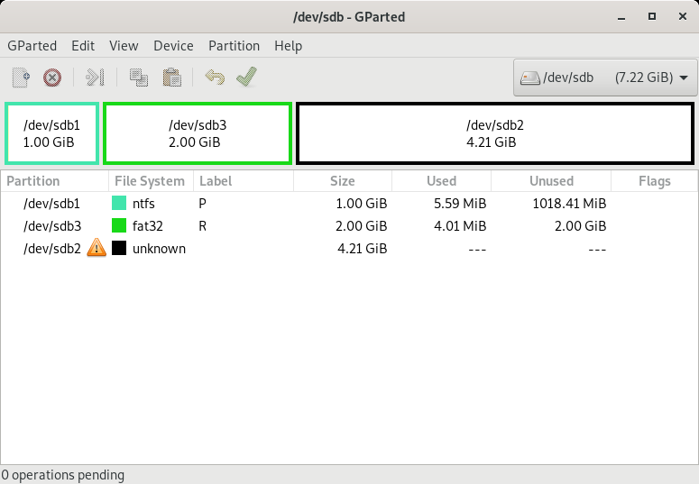
The test disk is partitioned into three volumes: one NTFS, one FAT32, and one unformatted Linux partition. This mirrors a real-world scenario where a disk may carry mixed file systems, which is common in dual-boot or multi-purpose environments.
The NTFS partition is created at 1GB and labeled "Pramuditha". In the MBR partition table, NTFS is identified by the type byte 0x07.
Creating a 1GB NTFS partition on sdb
GParted view confirming the 1GB NTFS partition labeled 'Pramuditha' has been created and formatted
The FAT32 partition is created at 2GB and labeled "Re". FAT32 uses type byte 0x0B in the MBR partition table.
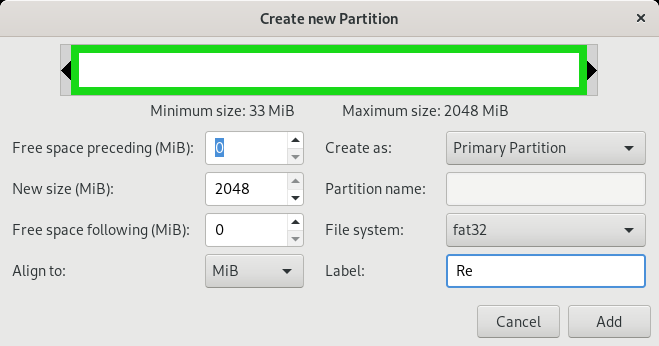
Creating a 2GB FAT32 partition labeled 'Re' on sdb
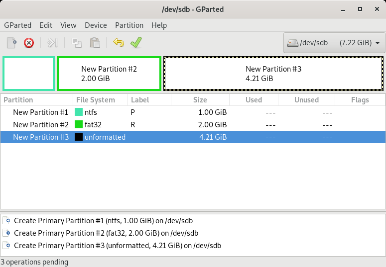
Partition details confirming the FAT32 volume size and label are correct
Disk overview showing all three partitions coexisting on sdb
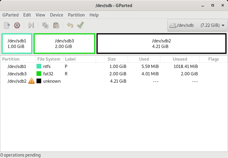
Final partition layout in GParted: NTFS (1GB), FAT32 (2GB), and an unformatted Linux partition
Reading the MBR Partition Table in Raw Hex
With the partition layout in place, the real forensic work begins. The MBR partition table occupies bytes 446 to 509 of the first sector. It contains four 16-byte entries, one per possible partition. Reading these bytes directly reveals everything about the disk layout without relying on any OS abstraction.
Each 16-byte partition entry follows this structure:
| Byte(s) | Field | Notes |
|---|---|---|
| 0 | Boot flag | 0x80 = bootable, 0x00 = not bootable |
| 1 to 3 | Starting CHS address | Legacy, no longer used in practice |
| 4 | Partition type byte | Identifies the file system (0x07 = NTFS, 0x0B = FAT32, 0x83 = Linux) |
| 5 to 7 | Ending CHS address | Legacy, no longer used in practice |
| 8 to 11 | Starting LBA address | First sector of the partition, in sectors |
| 12 to 15 | Partition size | Total number of sectors in the partition |
The raw hex dump of the partition table from the lab disk is shown below:
Hex dump of the MBR partition table at bytes 446 to 509, showing all four 16-byte partition entries
All multi-byte values in the MBR are stored in little-endian byte order. This means the bytes must be reversed before performing size calculations. To convert sector counts to bytes, the sector size of the disk must first be confirmed:
fdisk output confirming the disk uses a sector size of 512 bytes
Analyzing Partition 1
Boot flag byte: 00 -- not bootable. Type byte: 07 -- NTFS. Size bytes in little-endian: 00 00 20 00, reversed to big-endian: 00 20 00 00. Calculation: (16^5 x 2) x 512 = 1,073,741,824 bytes = 1GB. This matches the 1GB NTFS partition created earlier.
Analyzing Partition 2
Boot flag byte: 00 -- not bootable. Type byte: 0B -- FAT32. Size bytes: 00 00 40 00, reversed: 00 40 00 00. Calculation: (16^5 x 4) x 512 = 2,147,483,648 bytes = 2GB. This matches the 2GB FAT32 partition.
Analyzing Partition 3
Boot flag byte: 00 -- not bootable. Type byte: 83 -- Linux partition type. Despite this type code being present, the partition was never formatted, so no actual file system exists. Any OS will refuse to mount it. Forensic tools will see the partition entry but find no valid superblock or file system signature within it.
Hex dump confirming partition 3 carries type byte 0x83 (Linux) with no valid file system formatted inside
Partition 3 size bytes: 00 D8 86 00, reversed to big-endian: 00 86 D8 00. Calculation: (16^5 x 8 + 16^4 x 6 + 16^3 x 13 + 16^2 x 8) x 512 = 4,524,605,440 bytes = approximately 4.21GB.
Examining the NTFS Boot Sector
With the partition table understood, the focus shifts to the NTFS volume itself. Every NTFS volume begins with a boot sector that contains all the parameters needed to navigate the rest of the volume, most importantly the starting cluster address of the Master File Table.
Using FTK Imager, the boot sector of the NTFS partition is examined directly in hex view:
FTK Imager hex view of the NTFS boot sector: JMP instruction at offset 0x00, OEM ID 'NTFS ' at 0x03, BIOS Parameter Block starting at 0x0B, bootstrap code, and the 0x55AA end-of-sector marker at the final two bytes
The structures visible here match the NTFS boot sector specification precisely: the JMP instruction at offset 0x00, the OEM ID string "NTFS " at 0x03, the BIOS Parameter Block (BPB) beginning at 0x0B, and the 0x55AA signature at the final two bytes confirming a valid sector. Byte offset 0x30 (decimal 48) holds the starting cluster number of the MFT, which is the next destination in the investigation.
FTK Imager also exposes all NTFS metadata files, which the operating system keeps hidden from normal users. Seeing these directly is a fundamental part of forensic examination:
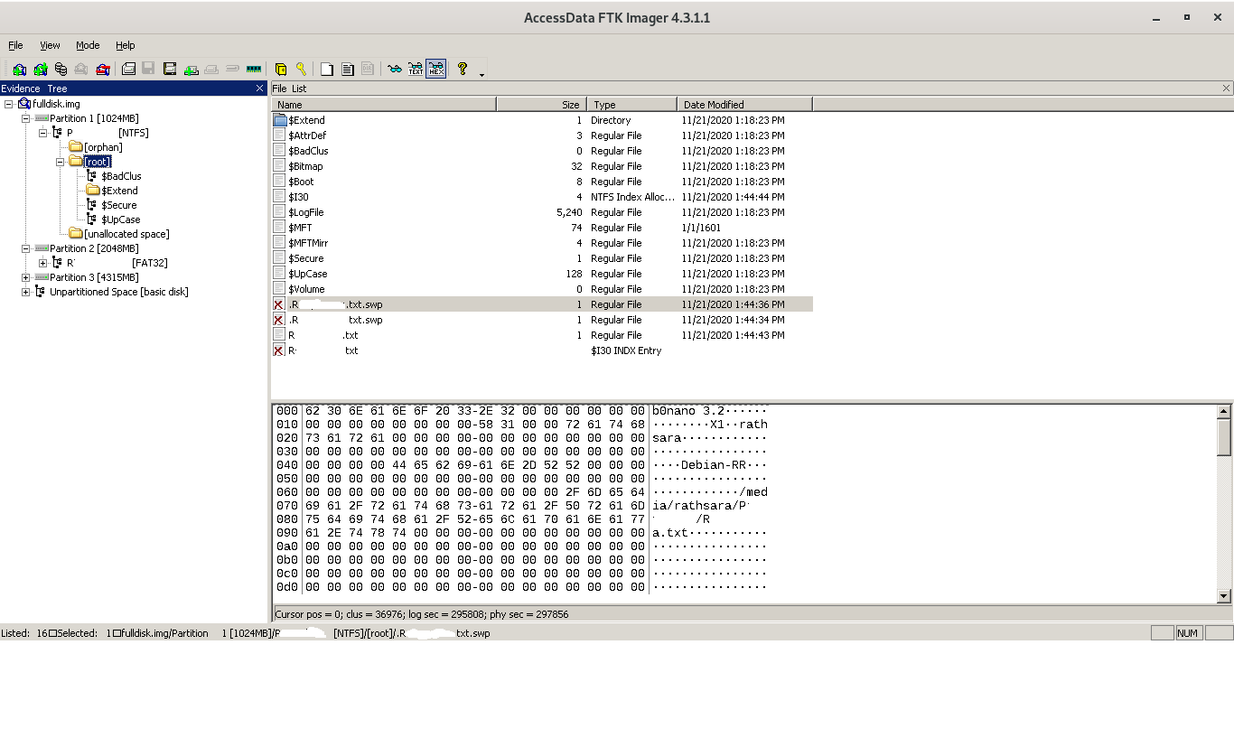
FTK Imager file tree showing all NTFS metadata files: $MFT, $MFTMirr, $LogFile, $Volume, $AttrDef, $Bitmap, $Boot, $BadClus, $Secure, $UpCase, and $Extend
The "Orphaned" directory that appears in FTK Imager is not part of the NTFS specification. It is an FTK Imager artifact: a virtual container used to group files that have been removed from the MFT index but whose data clusters have not yet been overwritten. It is one of the first places a forensic examiner should look when searching for deleted files.
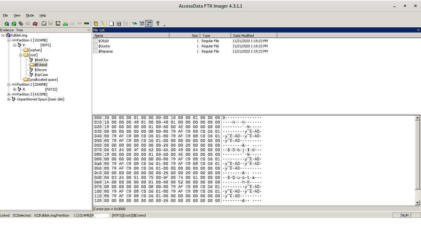
FTK Imager view of the $Extend directory, containing the $ObjId, $Quota, $Reparse, and $UsnJrnl metadata files
Locating a Specific File in the MFT
A small test file has been created on the freshly formatted NTFS partition. The partition contains no other files, making this an ideal controlled scenario for demonstrating how an examiner locates a file at the raw byte level.
The small test file visible in the Windows file browser before MFT-level analysis begins
Because the file is very small (a few bytes), NTFS stores its content directly inside the MFT record as a resident attribute, rather than allocating separate data clusters. The MFT is therefore the only place to look.
The starting point is the NTFS boot sector. It begins with the hex signature EB 52 (or EB 53 depending on configuration) and ends with 55 AA. Byte offset 0x30 within the boot sector stores the MFT starting cluster number, which allows the examiner to jump directly to the MFT without scanning the entire disk.
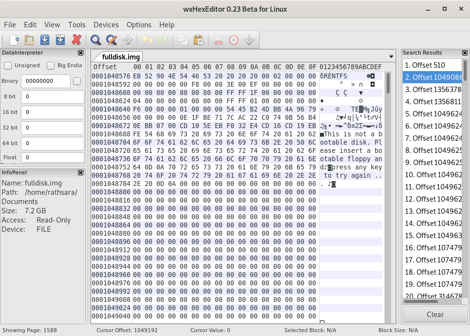
Hex editor view of the NTFS boot sector: EB 52 signature at the start, 55 AA end marker visible at the bottom, and the MFT start cluster address located at byte offset 0x30
Navigating to the MFT start cluster, individual records are identified by their "FILE" signature (46 49 4C 45). Since only one file exists on this partition, the target record is reached after scrolling through a small number of entries. Offset 44 (0x2C) within the MFT record header stores the record sequence number:
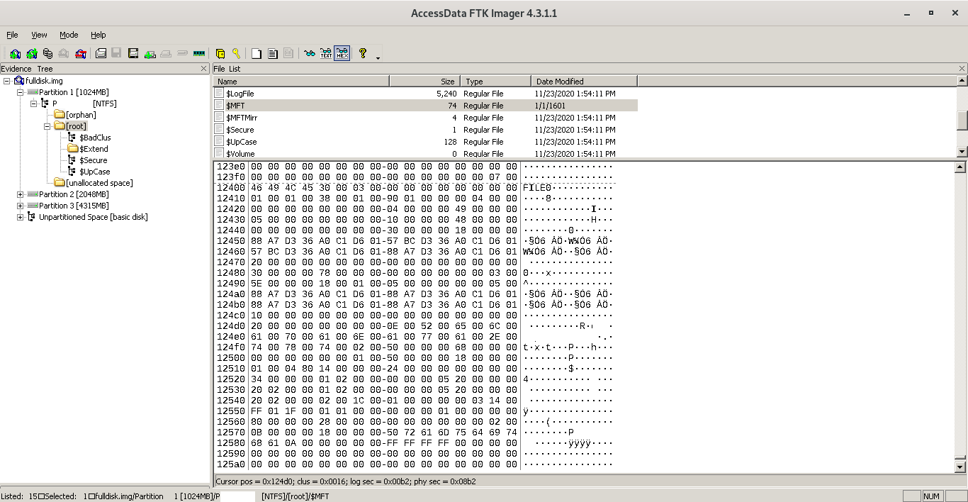
Hex editor view of the target MFT record: offset 44 contains the value 0x48 (decimal 72), identifying this as MFT record number 72
The value at offset 44 is 0x48, which is 72 in decimal. This file has been assigned MFT record number 72. Alternatively, if the file's creation or modification timestamp is known, filtering on offset range 80 to 111 (which stores four 8-byte FILETIME timestamps) provides another reliable way to identify a specific record in a densely populated MFT.
Key distinction: The MFT stores file metadata and, for small files, file content as resident attributes. For larger files it stores only a data run list pointing to the clusters on disk where the content lives. Knowing which type of record you are dealing with determines where to look next.
Detecting Deleted Files: What Changes at the Byte Level
This is where forensic analysis becomes especially revealing. When NTFS deletes a file, it does not erase the MFT record or overwrite the data clusters. It simply flips a flag. Understanding exactly which bytes change, and which do not, is what enables file recovery.
The Directory Index Before Deletion
NTFS maintains a B-tree index called \(I30 inside each directory. When a file is created, its filename and a reference to its MFT record are inserted into the parent directory's \)I30 index. This is how the OS builds the directory listing a user sees.
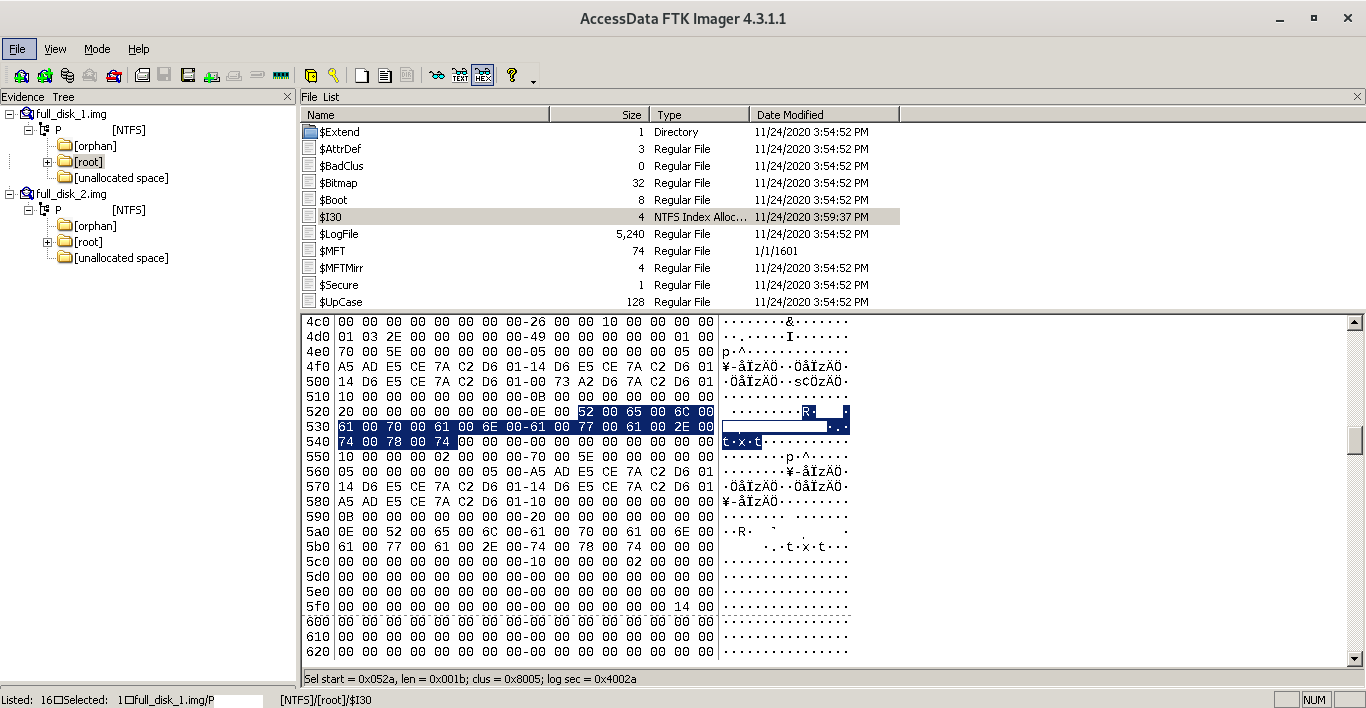
Hex editor view of the $I30 directory index at lines 520 to 540, showing the test filename and its MFT record reference inserted as an active entry
Once the file is deleted, the $I30 entry is removed:
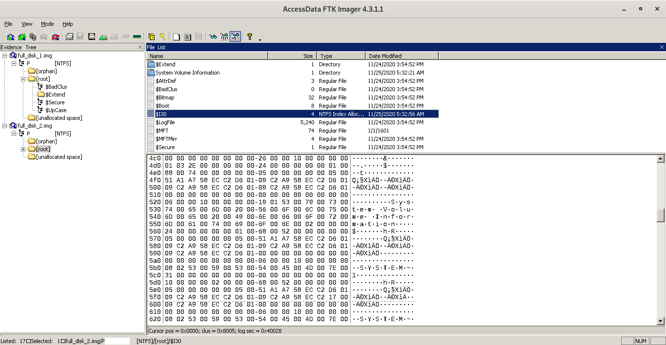
Hex editor view of the same $I30 region after file deletion: the filename entry has been zeroed out, but the surrounding structure remains intact
The gap or zeroed region left behind in the $I30 index is forensically significant. Recovery tools can identify these residual structures and reconstruct the original filename and MFT reference, providing a record of what was in the directory even after deletion.
The MFT Record Flag: Offset 22
Inside the MFT record itself, offset 22 (0x16) from the record start holds a single status flag that controls whether the record is considered active or available for reuse:
| Flag Value | Meaning |
|---|---|
0x00 |
Deleted file entry -- record is available for reuse |
0x01 |
Active file entry -- record is in use |
0x02 |
Deleted folder entry |
0x03 |
Active folder entry |
While the file is active, offset 22 is set to 0x01. The system will not allow any new record to overwrite this MFT slot:
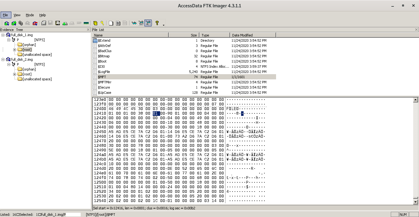
Hex editor view of the active MFT record: offset 22 reads 0x01, confirming this is a live file entry that cannot be overwritten
The moment the file is deleted, offset 22 is set to 0x00, marking the slot as free for future entries to claim:
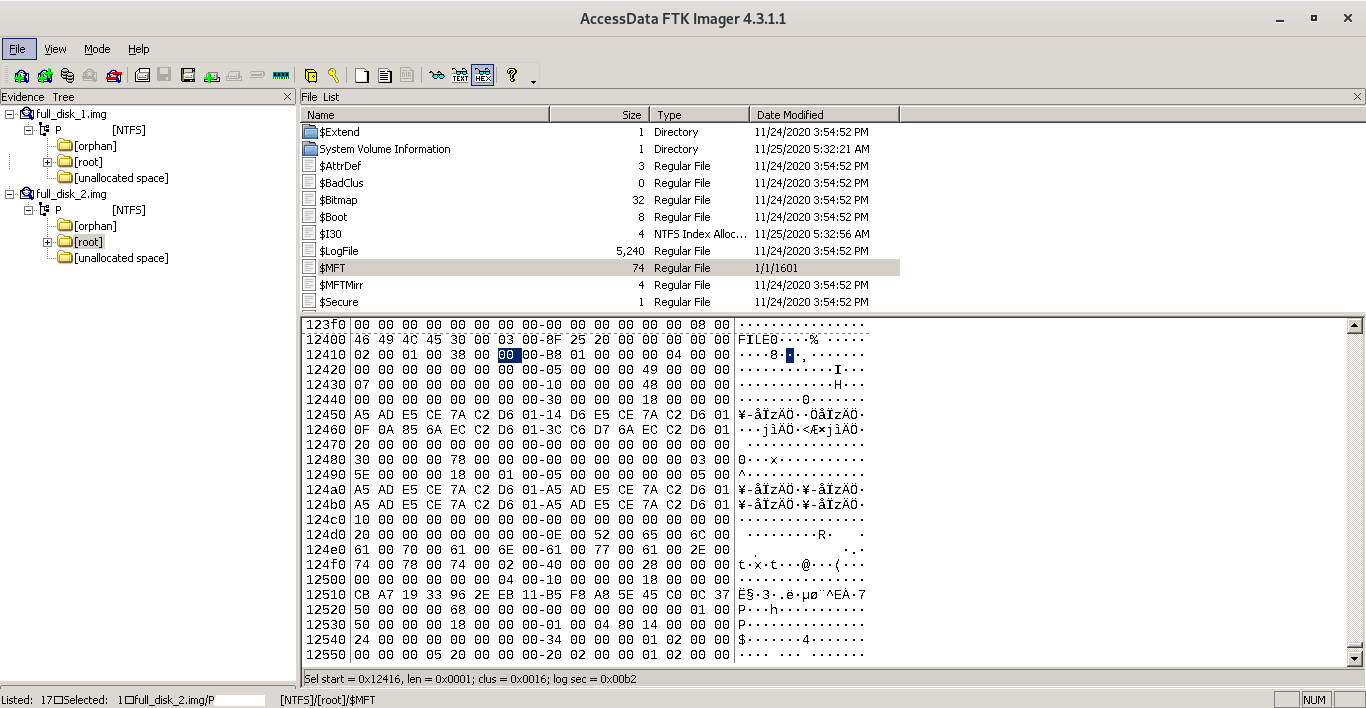
Hex editor view of the same MFT record immediately after deletion: offset 22 now reads 0x00, marking the record as available for reuse while all other data remains intact
Notice that the rest of the record is untouched. The filename, timestamps, data attribute, and data content (for resident files) all remain in place. Only the flag at offset 22 has changed. This is exactly why forensic recovery is possible: the OS does as little work as possible when deleting a file.
Other Byte-Level Changes on Deletion
Two further offsets change at deletion and serve as additional forensic indicators:
Offset 8 (Logfile Sequence Number): This value is updated to reflect the
$LogFiletransaction that processed the deletion. Before deletion it was all zeros; after deletion it carries a non-zero value such as8F 25 20(in little-endian). Comparing LSN values allows examiners to establish the relative ordering of file events.Offset 16 (Record Usage Count): This counter is incremented by one on deletion. It ensures the deleted record's sequence number cannot collide with any future record assigned to the same MFT slot, preventing false matches during recovery.
Offset 30 (Fixup Array): The fixup array value also increments on deletion as part of standard sector validation bookkeeping.
Challenges in Real-World Forensic Investigations
The controlled lab environment above makes file recovery look straightforward. Real investigations introduce complications that rarely appear in textbooks.
Data overwriting: The window for recovery closes the moment deleted clusters are reallocated and overwritten by new data. On an active system this can happen within seconds. When MFT records are overwritten, recovery shifts to file carving -- scanning raw disk sectors for known file signatures (magic bytes) -- which requires expert tooling and manual reconstruction.
Proprietary file systems: NTFS is licensed under Microsoft's proprietary license. Some internal behaviors are undocumented, and investigations involving undisclosed or vendor-specific file systems can leave examiners working with incomplete knowledge.
Cloud infrastructure: As organizations migrate to cloud platforms, physical storage is managed by third-party providers who will not expose internal architecture. Cloud forensics is a discipline still maturing, with significant legal and technical constraints on what an investigator can access.
Virtualization: Virtual machine disk images are stored as files (VMDK, VHD, QCOW2) within a host platform. Mounting and parsing these formats adds a layer of complexity, and careless handling risks corrupting the entire virtual environment.
Encryption: Properly encrypted data is statistically indistinguishable from random noise. Recovering deleted encrypted files without the decryption key is, for practical purposes, impossible. Investigation must focus on key acquisition through legal or technical means rather than direct decryption.
Solid State Drives: SSDs use wear-leveling algorithms and respond to TRIM commands that can make deleted data unrecoverable far more quickly than traditional spinning-disk HDDs. The proprietary nature of SSD firmware compounds this, as the internal mapping between logical and physical blocks is opaque to external tools.
Key Takeaways
MBR partition entries are 16 bytes each. The type byte at offset 4 identifies the file system. Size values are stored in little-endian and must be multiplied by the sector size to obtain a human-readable figure.
The NTFS boot sector at byte offset 0x30 points directly to the MFT start cluster, the entry point for all file-level forensic analysis.
Offset 22 within an MFT record is the single most important byte for determining whether a file has been deleted.
The
$I30directory index retains traces of deleted file entries even after the MFT flag is cleared, providing a secondary evidence path for recovery.Deletion in NTFS is a metadata operation, not a data erasure operation. Data clusters are marked available but not wiped, which is precisely what makes forensic recovery viable.
References
Carrier, B. -- File System Forensic Analysis
Microsoft Docs: NTFS Technical Reference
AccessData: FTK Imager User Guide
Part 2 of a two-part series on NTFS forensics. Part 1 covers NTFS file system internals, features, and volume structure.


